

 Nuclear Instruments and Methods in Physics Research A 455 (2000) 361-368

Results on photon and neutron irradiation of semitransparent
amorphous-silicon sensors
J. Cárabea, M.G. Fernándeza, A. Ferrandoa,*, J. Fuentesa,
J.J. Gandíaa, M.I. Josaa,
A. Molineroa, J.C. Ollera, P. Arceb, E. Calvob, C.F. Figueroab,
N. Garcíab,
F. Matorrasb, T. Rodrigob, I. Vilab, A.L. Virtob, A. Fenyvesic,
J. Molnarc, D. Sohlerc
aCIEMAT1, Fisica de Particulas, Edificio 2, Avda, Complutense 22, 28040 Madrid, Spain
bInstituto de Fisica de Cantabria, CSIC-Universidad de Cantabria2, Santander, Spain
cInstitute of Nuclear Research, ATOMKI3, Debrecen, Hungary
Received 15 March 2000; accepted 24 April 2000
Abstract
Semitransparent amorphous-silicon sensors are basic elements for laser 2D position reconstruction in the CMS
multipoint alignment link system. Some of the sensors have to work in a very hard radiation environment. Two different
sensor types have been irradiated with 60Co photons (up to 100 kGy) and fast neutrons (up to 1015 cm-2), and the
subsequent change in their performance has been measured. © 2000 Elsevier Science B.V. All rights reserved.
1. Introduction
In recent papers [1,2] the authors have introduced semitransparent amorphous-silicon (a-Si)
sensors for the 2D reconstruction of the position of the laser spots needed for CMS [3]
alignment system [4]. These sensors are basic elements of the multipoint link alignment
subsystem that relate the position of the muon chamber stations [4] to that of the central
tracker [5]. The final choice on this type of sensors is still pending on final tests [6],
in particular, those related to their radiation endurance. Some of the sensors will be
located in regions where the irradiation will be as high as 10 kGy/yr, neutron fluences up to 1014/cm2
and year and charged-hadron fluences of about 1013/cm2 and year [3]. Fig. 1 gives a schematic view
of the CMS detector showing the location of the 2D transparent sensors.
We recently [7] irradiated two different sensors, one having a single a-Si layer (Schottky sensor) and
a second one constructed with 3 a-Si layers (p-i-n sensor), with gamma rays from 60Co sources at the
NAYADE facility at CIEMAT (Madrid, Spain), up to a total of 100 kGy (equivalent to about 10 years of
CMS operation). The optical properties of both sensors: light deflection and transmittance were measured
as functions of the dose absorbed. The Schottky sensor was equipped with electronics allowing to measure
the response to a uniform white light [7].
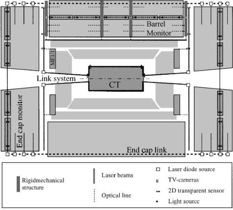
Fig.1.Longitudinal view of the CMS detector, showing the different alignment systems and the position of the 2D sensors.
2. Experimental conditions
The Schottky sensor (see Fig. 2) consists of a layer of hydrogenated amorphous silicon of about 1 μm
thickness sandwiched between two layers of about 100 nm of ITO (indium-tin oxide), perpendicularly
segmented to draw a 2D transparent matrix of 64×64 strip electrodes. The sensor layers are deposited
using Chemical-Vapour-Deposition (CVD) techniques. The indium-tin oxide is segmented using photolithographic
methods. Strip pitch is 312 μm and strip gaps are 10 μm wide. The three layers (ITO, a-Si and ITO) are
deposited onto a 0.5 mm-thick glass substrate. Laser light is partially absorbed by the a-Si material
producing photocurrents extracted through the strips. These photocurrents are multiplexed, converted
into voltages and transferred to the ADC of the microcontroller.
The p-i-n sensor has the same geometry, but has three a-Si layers instead of a single one: respectively,
p-type doped, intrinsic and n-type doped. Doped layers are 10-20 nm thick.
In both cases the strip layout allows to have two orthogonal projections of the incoming beam.
Vertical strips reproduce the projection of the beam spot (typical section is 2-3 mm) along
the X-coordinate while horizontal strips do the same along the Y-coordinate.
2. 1. Sensor structure
The semitransparent amorphous-silicon sensors studied here were first developed at the Max Planck
institute of Munich [9] and commercialized by EG&G Optoelectronics [10].
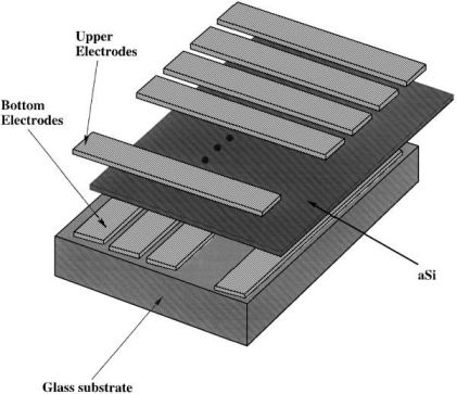
Fig. 2. Drawing of the Schottky sensor showing the layer arrangement.(The drawing is not scaled.)
2.2. Irradiation
The photon irradiation [7] was done at the NAYADE facility of CIEMAT, Madrid. We used
60Co sources delivering a total flux of 3 kGy/h. The total dose was 100 kGy, which corresponds to
the expected accumulated dose after 10 years of CMS operation at the maximum luminosity
(1034 cm-2 s-1).
The irradiation was done in steps of 100 Gy and 10, 15 or 20 kGy. Photon energies from 60Co are 1.17 and 1.33 MeV.
The neutron irradiation was done using the fast neutron source based on the MGC-20 cyclotron facility available
at ATOMKI, Debrecen. The neutrons were produced by p(18 MeV)+Be reactions.
The mean energy of this broad spectrum source was 3.7 MeV with a typical flux of 1.6× 109 cm-2
s-1. The spectral
intensities and the angular distributions of this neutron source [11] were used to plan the irradiations.
Neutron transport calculations were also carried out using the MCNP-4B transport code [12] in order
to prepare the geometry for irradiation. An aluminium disk, with 13 mm diameter and 0.76 mm thickness
was placed behind the sensors during the irradiations and the 27Al(n,α)24 Na
reaction was used as a fluence monitor.
The total neutron fluence was (1.1 × 10¹⁵±37%) cm-2, equivalent to 10 years of CMS operation at the maximum
luminosity. The irradiation was done in two exposure periods: first a fluence of (1014±12%) cm-2,
followed, a few months later, by a second dose of (1015±37%) cm-2 in three fractions.
The last three fractions can only be delivered in the target neighbourhood (∼70 mm sample} source distance)
where the longitudinal and transverse gradients of the neutron field were rather high. For these fractions,
the sources of the large uncertainty on the total neutron fluence are: (1) the uncertainties on the sample
positioning during the three fractions (∼15%), (2) the flux heterogeneity (∼15%), (3) the fluctuations of
the current density distribution of the incident proton beam (∼5%), (4) the uncertainties on the activity
measurement (∼12%), (5) the uncertainties on the nuclear data used (∼10%) and (6) the uncertainty on the
estimation of the neutron fluence below 0.3 MeV (∼25%).
The spectrum of the associated photons cannot be measured directly and, therefore, precise calculations
of the dose absorbed by the sample is not feasible. However, an additional dose of 5 kGy± 37% can be estimated
from the human muscle equivalent material using the so-called twin-chamber technique [13].
2.3. Optical measurements: Experimental setup
In order to check the optics over the whole active surface (∼2×2cm2), the sensor under test is placed
on two motorised platforms (one vertical and the other horizontal) and data are taken over a 16×16 matrix
of points (1 mm pitch). The motorised platforms have 2 µm resolution.
The transmittance to the HeNe wavelength is calculated as the ratio between the signal read from the
second sensor when the first one is in the light path and that in the absence of the first sensor. This
method is very sensitive to any laser intensity instabilities and has a typical 10% uncertainty.
For the response test of the Schottky sensor, a white light from a halogen lamp mounted in the focus
of a dichroic reflector and coupled to a diffuser was used to illuminate the whole surface.
The monitoring of the halogen lamp was done with a photocell whose induced photocurrent intensity had
previously been calibrated. Fig. 3 shows the irradiance of the lamp as a function of the measured current
intensity in the photocell. Data points include measurement errors. The solid line represents a fit of the
data points to the function
E(mW/cm2) = (6.02±0.01)×I(mA)+(-0.03±0.08).
The white-light spectrum, in terms of the irradiance as a function of the wavelengths emitted by the lamp, is shown in Fig. 4.
The experimental setup for optical measurements, consisted of a HeNe (633 nm) laser, the sensor under test,
located at a distance of about 0.6 m from the laser, in the light path, and a second position detector
(a Schottky sensor) located 2.58 m downstream the first sensor. The second sensor reconstructs the light
spot and measures the deflection angle originated by the first one, by measuring, in advance, the position
of the laser light spot in the absence of the first sensor.
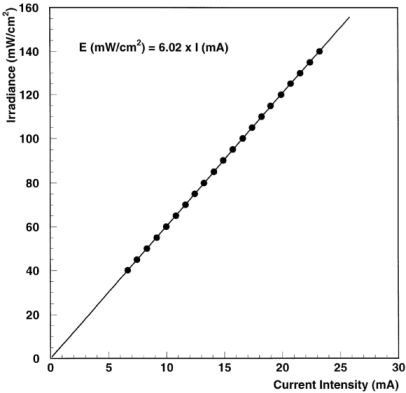
Fig. 3. Photocell calibration (see text).
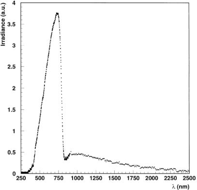
Fig. 4. Halogen lamp irradiance spectrum.
3. Results
The deflection angle distributions do not have Gaussian shapes [1,2]. Figs. 6 and 7 show the
surface-averaged values of the deflection angles, for the Schottky and the p-i-n sensors,
respectively, as functions of the accumulated dose. Angles are given in μrad. The last two
points in the plots correspond to 100 kGy photon irradiation plus 1014 and 1015 neutrons/cm2.
The error bars represent the r.m.s. of the angular distributions. There is no appreciable
change along the irradiation.
3.1. Deflections
Keeping the position of the laser fixed, the sensor under test was scanned over its whole surface using the
motorised platforms. The X and Y positions of the light spot were reconstructed on the farthest sensor.
The difference with respect to the reference position (the reconstructed light spot in the absence of the
sensor under study) was calculated and divided by the distance between both sensors. In this way,
the X (Θx) and the Y (Θy) components of
the deflected angle were measured for all the points taken during the active surface scan. Fig. 5
shows the deflected angle Θ schematically.
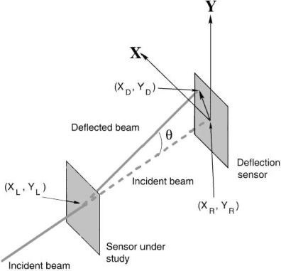
Fig. 5. Sketch of the deflection angle measurement.
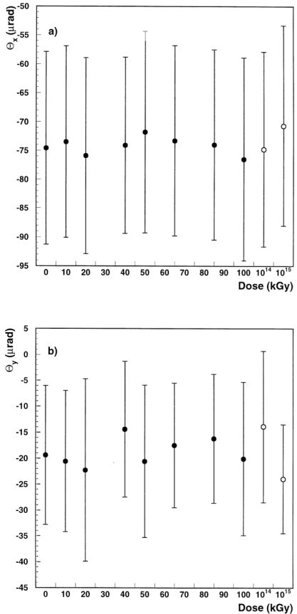
Fig. 6. For the Schottky sensor, mean values of the deflection angles as a function of the absorbed dose(see text): (a)
Θx, (b)
Θy.
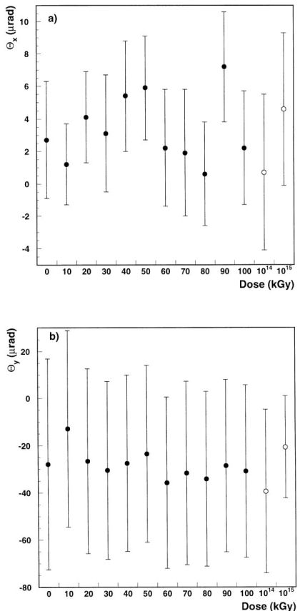
Fig. 7. For the p-i-n sensor, mean values of the deflection angles as a function of the absorbed dose(see text): (a)Θx, (b)Θy.
3.2. Transmittance
Using the HeNe laser, the measured transmittances as functions of the absorbed dose, are given in Figs. 8(a)
and (b), for the Schottky and the p-i-n sensors, respectively. The transmittance is calculated at each
point of the scanned surface and averaged, the error bars represent the r.m.s. of the corresponding
distributions. The last two points on the right in Figs. 8(a) and (b) correspond to 100 kGy photon
irradiation plus 1014 and 1015 neutrons/cm2.
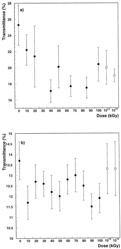
Fig. 8. Transmittance as a function of absorbed dose (see text): (a) Schottky sensor, (b) p-i-n sensor.
3.3. Electronics
For measurements after each irradiation step we reinserted non-irradiated multiplexers that
had been unwelded and removed prior to the irradiation. Since the laboratory was not completely
dark, a first measurement was done with the uniform light source off. Then, the lamp was switched on,
the irradiance was measured with the photocell and
new data were taken. The response from every strip was recorded and the background subtracted.
The values measured were uniform among the strips.
Mean values are:
4. Comparison between irradiated and non-irradiated Schottky sensors
The Schottky sensor was equipped with some nearby electronics
located on its frame, consisting
of multiplexers, resistors and capacitors. The multiplexers were DG406 (16-1) from SILICONIX.
All of them were destroyed after an accumulated dose of 200 Gy photons (two irradiation steps).
However, resistors and capacitors were still working after the completion of the irradiation
(photons plus neutrons). The resistors are surface-mounting devices (SMD), made of nicrom
packaged in ceramics, with a resistance of 47 kΩ. They act as bias resistors for the sensors.
The capacitors are multilayer ceramics SMD. Their capacitance is 0.1 μF. They act as multiplexer
bypass capacitors.
3.4. Response
The response of the Schottky sensor was measured before starting the gamma irradiation and
after a few steps, using a uniform white light (see Section 2.3). These measurements were done
illuminating the sensor through the glass substrate face and with an irradiance of 0.16 mW/cm2.
Measurements after each neutron irradiation step were done in the same experimental conditions.
The time lapse between neutron irradiations and measurements was about 1 month and therefore
some annealing processes most probably took place even at ambient temperature.
S(ADC counts) = 196.1±4.1 before irradiation
S(ADC counts) = 195.9±3.9 at 200 Gy
S(ADC counts) = 174.6±4.6 at 10 kGy
S(ADC counts) = 176.9±4.9 at 100 kGy
S(ADC counts) = 140.4±8.0 at 100 kGy and 1014 neutrons/cm2
S(ADC counts) = 121.9±7.2 at 100 kGy and 1.1×10¹⁵ neutrons/cm2.
As from 10 kGy a degradation of about 10% is detected. The 1014 cm-2 neutron irradiation adds a 20%
additional decrease in the sensor response, and further 1015 cm-2 neutrons still decrease the signal
by another extra 15%. In total, the signal after the 100 kGy photons and the 1.1×10¹⁵ neutrons/cm2,
represents about 60% of the original one.
For completeness we have compared the response and the trasmittance, with uniform white
light, of the irradiated sensor with those measured on two other Schottky, non-irradiated, sensors.
4.1. Response
The sensors were illuminated with the uniform white light (2.3) on both faces. The irradiance was
kept constant at 0.46 mW/cm2, close to saturation, to increase the output current.
The comparison is shown in Fig. 9. The figure is divided into two parts: on the left hand the
results after illumination of the sensitive face, on the right hand the measurements done
illuminating the sensor through the glass substrate face. Labels A, G and D are arbitrary
names for the three sensors. Letter D corresponds to the irradiated one. D14 and D15
correspond to the measurements
after 100 kGy photons and 1014 and 1015 neutrons/cm2, respectively.
Data points are the average values of the signals read from the 64 vertical (v) and the 64 horizontal
(h) strips. Error bars are the r.m.s of the corresponding distributions. Data show, in general, a
good response uniformity among strips. Sensor D shows a clear response degradation after
the 1015 neutrons/cm2 irradiation step.
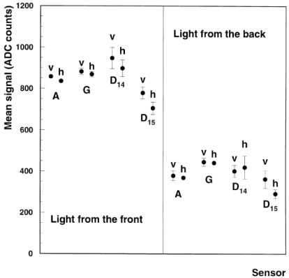
Fig. 9. Comparison of the responses of non-irradiated (A and G) and irradiated (D) Schottky sensors (see text).
Using the white-light source we have measured the transmittance of the irradiated and
the non-irradiated Schottky sensors by installing the photocell in front of and behind
the sensors. The intensity of the current in the photocell is measured in both positions
and the ratio is taken as the transmittance of the sensors to the integrated white-light
spectrum in Fig. 3.
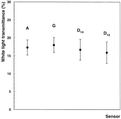
Fig. 10. Comparison of the transmittace of non-irradiated (A and G) and irradiated (D) Schottky sensors (see text).
5. Summary and conclusions
Two commercially available semitransparent amorphous-silicon sensors have been irradiated
with photons up to 100 kGy and with neutrons up to 1015 cm-2. These sensors are foreseen
to be used for multipoint alignment systems and the measurement of the irradiation-induced
changes in their performance has allowed us to draw the following conclusions:
No variation in the deflection-angle spreads were observed. There are indications of a small
degradation (5-10%) in the transmittance when using an HeNe laser light (633 nm). This
variation is nevertheless compatible with the measurement uncertainties.
The illumination of the Schottky sensor on the substrate face, using a uniform white
light, after several steps along the irradiation, shows a degradation of about 40% in
the response measured at the strips, after 100 kGy photon radiation and 1015 neutrons/cm-2.
From the comparison of the response and transmittance of the irradiated sensor to those
of two other Schottky, non-irradiated devices, it has been concluded that their responses
and transmittances to a uniform white light, are not inconsistent, within the errors.
This fact evidences that the construction of sensors is not very uniform, but also,
that the irradiation (up to the doses applied) will not spoil sensor performance for
the application foreseen.
The resistors and capacitors used remain operative after 100 kGy photons
and 1015 neutrons/cm-2 Currently available multiplexers are destroyed after 200 Gy photons.
References
[1] J. Berdugo et al., Nucl. Instr. and Meth. A 425 (1999) 471.
[2] M.G. Fernández et al., Nucl. Instr. and Meth. A 440 (2000) 372.
[3] The CMS Collaboration, The Compact Muon Solenoid Technical Proposal, CERN/LHCC 94-38.
[4] The CMS Collaboration, The Muon Project Technical Design Report, CERN/LHCC 97-32.
[5] The CMS Collaboration, The Tracker Project Technical Design Report, CERN/LHCC 98-6.
[6] The Link and Endcap Alignment Groups, Status on the choice of the Digital Position Sensing Detectors
for the Muon-Alignment System, CMS Document, 1999-042.
[7] M.G. Fernández et al., Nucl. Instr. and Meth. A 439 (1999) 111.
[8] A. Fenyvesi et al., Z. Medizinische Physik 1 (1991) 1.
[9] W. Blum, H. Kroha, P. Widmann, Nucl. Instr. and Meth. A 367 (1995) 413.
[10] EG&G Optoelectronics, 45 William Street, Wellesley, MA, USA.
[11] M.A. Lone et al., Nucl. Instr. and Meth. A 143 (1977) 331.
[12] J.F. Breismeisteir, MNCP-A General Montecarlo N-particle code, LA-12625-M,
Los Alamos National Laboratory, March 1997.
[13] J.J. Broerse et al., Br. J. Radiol. 54 (1981) 882.
* Corresponding author.
E-mail address: ferrando@uael.ciemat.es (A. Ferrando).
1Under CICYT (Spain) grant: AEN99-0312.
2Under CICYT (Spain) grant: AEN99-0571.
3Under OTKA Grant: T026184.
0168-9002/00/$-see front matter © 2000 Elsevier Science B.V. All rights reserved.
PII: S0168-9002(00)00516-7
